
Electrical Actuators
Wiring Diagram
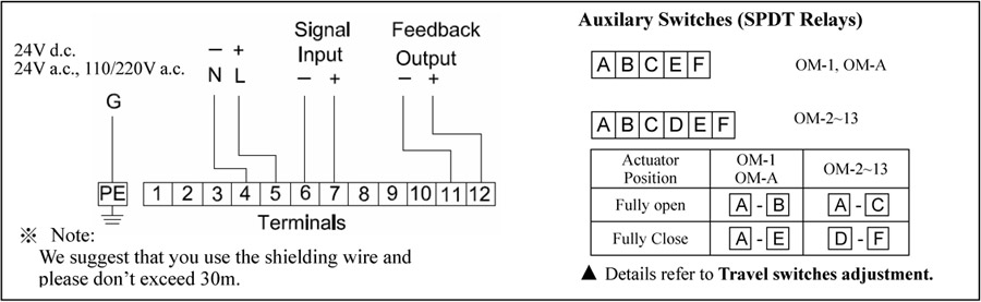
OM-1 ~ OM-13, OM-A, OM-A-M, BM-2 110/220/24V Actuator (ON/OFF, 3 Point Control)

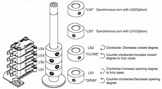
Travel switches adjustment for OM-2~OM-13
The quarter-turn actuator is provided with a limiting of manual rotation device to avoid over-travel with the hand-wheel. Before setting the limit switches, please adjust the mechanical stops.
Mechanical Stops adjustment
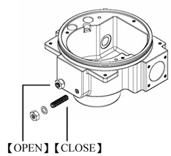
1. To loosen the screws
2. To adjust limit switches & travel cams.
3. To adjust the screws
4. To reverse one cycle
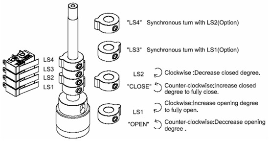
Travel switches adjustment for OM-1 & OM-A, OM-A-M
Important Notices & Maintenance
- Make sure if the voltage is correct before wiring.
- Power off before distribution or for maintenance purpose.
- Lock tight the casting and conduit entrance after power distribution to prevent from dusting or water spoiling.
- The angle of electric actuators must not be below the horizon or stands upside down.
- When electric actuators need two sets of unit for simultaneously, please connect with the individual cable.
- Don’t install in complete vacuum space directly.
- Actuator should be placed at clean and dry place for storage, and protected with outer carton from being affected by great temperature difference or serious vibration.
OM-1~ OM-13, OM-A, OM-A-M 110/220/24VActuator (Modulating , 30% & 75% duty cycle)
Wiring Diagram
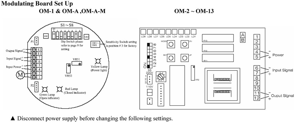
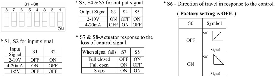
Dip Switch setting
sensitive switch: (Factory setting is position “3”)
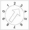
Position “0” : Lowest Sensitive, 0-90 divided into 17 steps.
Position “1” : Highest Sensitive, 0-90 divided into 70 steps.
Setting for OPEN and CLOSE
|
|
To reset and return to the original status – Please power off and get troubleshooting, then power on.